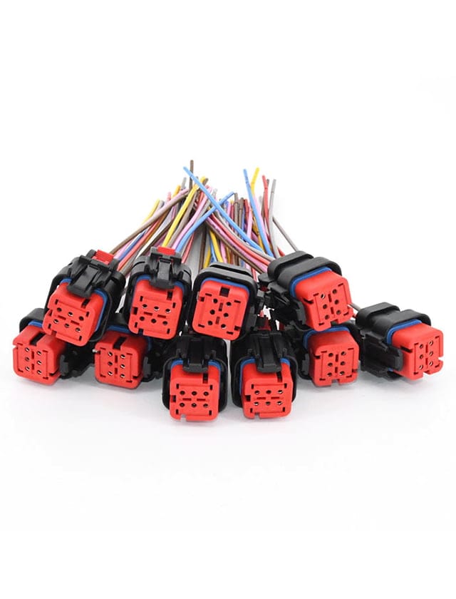
What Sectors Use Custom Plastic Injection Molded Connectors
Some things need unique Plastic Injection Molded Connectors to stay together. These pieces are made very carefully to fit just right. They are super strong and last a long time. Many places need these pieces so machines, tools, and other things can work correctly. These unique pieces make sure things don’t break and stay in place. Let’s look at all the areas that need them! Vehicles Need Plastic Injection Molded Connectors to Work Cars, trucks, and buses have lots and lots of little parts inside them! molded connectors help these big machines run. They help lights turn on, doors lock, and radios play music. These small plastic parts are super special! They are light, so cars do not have to work too hard. They do not get rusty, even when it rains or snows. That means cars last a long, long time! If cars did not have molded connectors, they would break faster and cost more to fix. These little plastic parts help cars be strong and safe! Hospitals use Plastic Injection Molded Connectors Doctors and nurses use special machines to help sick people get better. Molded connectors are inside these machines to help them work! They are in heart monitors, X-ray machines, and even tiny hearing aids. These pieces must be super strong and very clean. If they were dirty or broken, the machines would not work right! That would be bad for sick people. molded connectors help doctors and nurses save lives every day! Molded Connectors are Also In smart Gadgets Phones, TVs, computers, and video games all need molded connectors to work! These small parts help buttons turn on, and screens light up. Without them, headphones would not play music, and smartwatches would not tell time. These plastic parts also stop things from getting too hot and...
Read More »Use Cable Assemblies in the best and simplest ways
Cable Assemblies help things work. But they need to be used correctly so they do not break. They will last longer and work better if you take care of them. There are simple steps to keep wires safe and strong. If cables are put in place correctly, they will not get damaged. Good wire care means things will work better for a long time. Pick the Very Best Cable Assemblies for What You Need Cables are like magic strings! They help things work! Some cables bring power, like the power that makes lights turn on, and computers work. Some cables move things, like pictures, sounds, and words! Every cable has an exceptional job! If you pick the wrong one, things will not work right. That is not fun at all! Picking the right one makes everything easy and happy! Look at how long the cable is! If the cable is too short, it will not reach where you need it! That is super frustrating! If the cable is too long, it can get all messy and tangled like a big spaghetti pile! You do not want to trip over messy wires! That is not safe! Pick strong Cable-Assemblies, too! Some Cable-Assemblies are robust and can fight heat, water, and bumps! That helps them last a long, long time! Check the ends of the cable! The wrong ends will not fit! That means you cannot plug them in! That is a big problem! Ensure the cable you pick has the proper ends so everything fits perfectly! A suitable cable makes everything easy, smooth, and happy! How to Keep Your Wires Neat and Nice Messy, tangled wires are not good at all! They twist and turn and get all jumbled up! That can make them break! And if they fail, nothing...
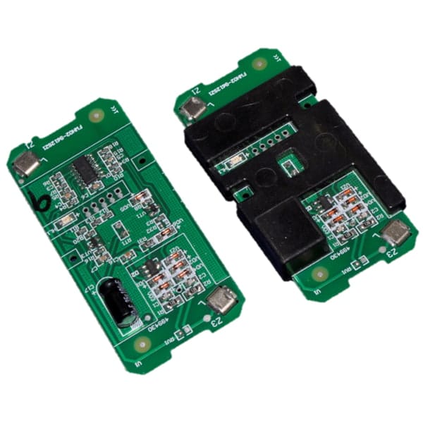
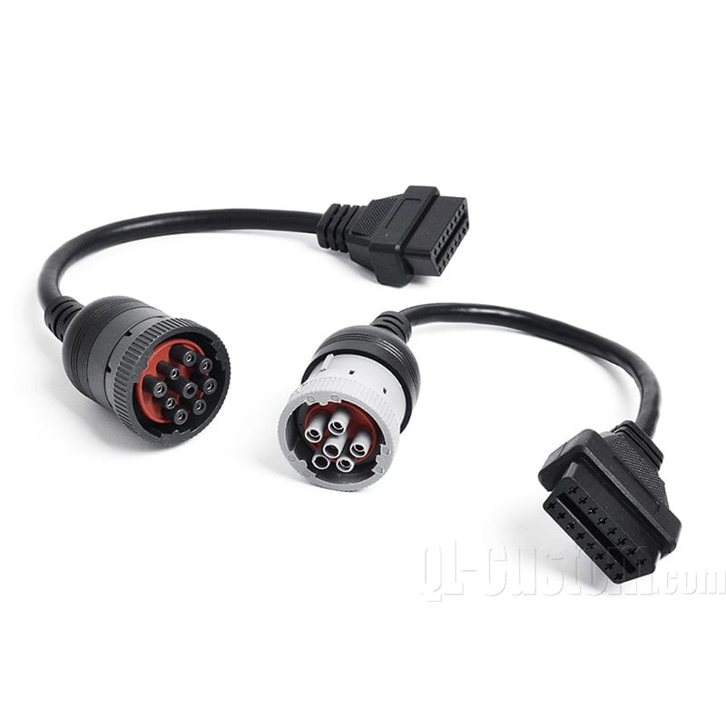
Read More »Is a Custom OBD connector a vital part for machines
Cars and machines need to know if something is wrong. But how can they tell? A special plug called a Custom OBD connector helps them talk! This plug tells people if a car or machine needs fixing. It makes sure everything runs smoothly and does not stop working. When cars and machines have problems, this plug helps fix them fast! Let's see why this little plug is a very, very big deal! What is a Custom OBD connector? An OBD plug is a super special spot on cars, trucks, and big machines! It is like a tiny helper that tells you when something is wrong. When a machine is feeling sick, the OBD plug sends a message, like a bit of alarm, saying, "Help! Fix me!" This is super good because it helps people know what is wrong before things get terrible. When a special OBD plug is used, it works even better. It makes sure that machines send the best and most precise messages. This means machines can stay happy and work really well for a long, long time! Why a Special Custom OBD Connector is Needed Not all machines are the same! A regular OBD plug is made for most cars, but other machines need something just right for them. A special OBD plug is made to fit perfectly. It makes sure everything connects right. It helps machines talk to tools in the best way, with no mistakes at all. This makes fixing problems super fast, super easy, and super good. Machines can keep working without stopping too much, and that is awesome! Why a Special OBD Plug is Super Helpful Finds Problems Fast: A special OBD plug helps find problems really, really fast! That means no long waiting. No guessing. No big worries. Fits Just Right: Special...
Read More »Sectors that Use Custom Low Pressure Molding
Some things need Low Pressure Moldings so they do not break or get hurt. These covers help things last a really, really long time! They keep things secure from bumps, water, and dirt. Big jobs like making cars, building big machines, and making tiny computer parts all use these. Without covers, things could break too fast! Let's learn more about who needs these covers and why they are so important! Low Pressure Molding Helps Phones & Computers Stay Strong Phones and computers have lots of tiny, tiny parts inside. These parts are super important because they make everything work. But these little parts can get hurt very easily. If water splashes on them, they can stop working. If dust gets inside, they can break. If they get bumped or dropped, they might stop working forever! That would be really, really bad! Low-pressure molding makes a super strong cover around these tiny parts. It wraps them up like a warm, safe blanket. It keeps them dry. It keeps them clean. It keeps them safe from bumps and drops. This helps phones and computers last a long, long time! That means people can watch their favorite videos, play fun games, and talk to their friends without any problems. Low Pressure Molding Helps Cars Keep Moving Cars have lots and lots of little wires and tiny parts inside. These parts help the car move, stop, and turn. They make sure the car's lights turn on. They make sure the engine works. But these little parts need to stay safe! If water gets in, they can stop working. If dirt gets inside, they can break. If something terrible happens to them, the car might stop moving! That would be super scary! It makes a strong, tough cover that keeps these little parts safe. It...
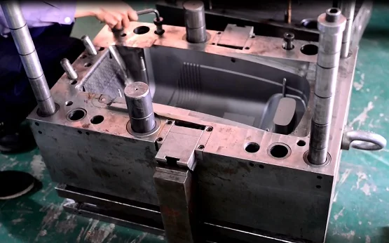
Read More »Are there Benefits of Custom Plastic Injection Molding

Machines have lots of little parts. Some of these parts are made of plastic. People use a big machine to melt plastic and press it into a shape to make plastic parts. This is called Custom Plastic Injection Molding! Plastic moulding helps make parts the same size and shape every time. That way, every part fits just right. It also costs less than making parts by hand. Plastic parts made this way are strong and last a long time. Let’s learn why plastic moulding is so helpful! How Do We Make Plastic Pieces That Fit Together? Plastic pieces need to fit together like a puzzle! They cannot be too big. They cannot be too small. They need to be just right! Plastic injection moulding makes every piece the same shape and size. This means no mistakes! No wobbly parts! Every piece will match and work perfectly, just like magic! Factories use this method to make substantial plastic parts for many things, like toys, machines, and cars. Custom Plastic Injection Molding: Make So Many Pieces Making plastic pieces this way helps save lots and lots of money. First, we make a unique mold. Then, we can use it repeatedly to make thousands, even millions, of pieces! We do not have to wait a long time for each one. We can make so many pieces super fast! This also means we do not waste extra plastic, and that helps save even more money. Less waste is better for the earth, too! Strong and Tough Plastic Pieces That Last a Long These plastic pieces are not weak! They are powerful! They do not break easily. They do not melt when it is hot. They do not crack when it is cold. They stay in good shape for a very, very long time! That...
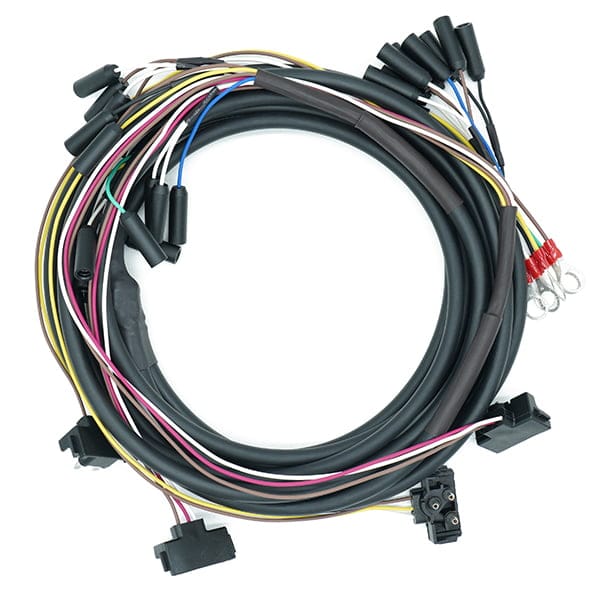
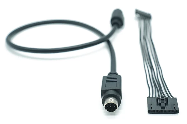
Read More »Benefits of Using a Custom Wire Harness in Electronics
Wires are tiny ropes that carry power to machines. When wires are all over the place, they get messy and can break. If a wire breaks, the machine may stop working. That is bad! A Custom Wire Harness is a way to keep wires safe. The wires stay in one place and do not get tangled. That means machines can work better and last longer. It also helps people stay safe. Let’s learn why wire bundles are super helpful for machines. A Custom Wire Harness Helps People Save Time A wire harness bundle is a bunch of wires in one neat and tidy group. When wires are all loose, they can get messy and complicated. But they stay nice and neat when they are in a wire bundle. This makes it so much faster to set things up. People do not have to guess where each wire goes because everything is already in the right spot. It also helps to stop mistakes. If the cables are not mixed up, everything will work just right. That means no problems, no worries, and no time wasted! Custom Wire Harness Keeps Wires Neat If wires are loose, they can turn into a big, big mess. They can twist, tangle, and get all mixed up. That makes it hard to know which wire goes where. A wire bundle stops this from happening. It keeps all the cables in one place, all neat and tidy. This makes it so much easier to work with. It also helps if something breaks because people can find the correct wire fast. No more guessing or searching—everything is right where it should be! Custom Wire Harness Keeps Wires Safe from Water Wires need to stay safe to work the right way. They can break if wires get wet, dirty,...
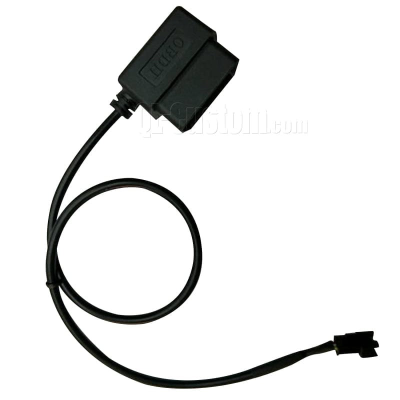
Read More »How do OBD Cables help troubleshoot vehicle problems
OBD cables are tools to help cars. They connect the vehicle to a machine. This machine finds problems inside the car. It shows codes that tell what is wrong. This makes fixing the vehicle easy and fast. OBD wires save lots of time. They help mechanics fix cars quickly and satisfactorily. What Are OBD Cables and How Do They Help Your Car? OBD connectors are little plugs that help find what is wrong with your car. They are like a bridge between your vehicle and a tool that checks for problems. The car’s computer saves clues when something is wrong. The OBD connector lets the tool read these clues. This helps mechanics, or even you, know what needs fixing. It makes fixing cars faster and easier. Without this, it would take a lot more time to figure out what is wrong. How Do OBD Connectors Help Find Car Problems? Your car has a little computer inside. This computer checks if everything is working fine. If something is broken, it saves a code. The OBD plug helps read this code. When you connect the plug, the tool shows the code on its screen. It’s like the car is talking to you, telling you what’s wrong. This makes fixing the vehicle easy. It saves time because you don’t have to guess. It helps everyone, from drivers to mechanics. Why Are OBD Power Pins So Important? The OBD power pins are small parts, but they do a big job. They give power to the tool that checks your car. Without these power pins, the tool will not turn on. That means it won’t work. The pins make sure the tool has the energy it needs. If the pins are broken, you can’t read what’s wrong with the car. They may be tiny, but...
Read More »Can Technomelt Hotmelt Resins be used for automotive works
Technomelt hotmelt resins are like glue for car parts. They stick parts together very well. They can handle lots of heat and stay strong. They fill spaces and stop leaks. This helps make cars safer and better. These resins work in hard places and last a long time. They keep car parts safe and in place. What Are Technomelt Hotmelt Resins? Resins are like sticky glue. They hold things together. Hotmelt resins are robust and work well. They melt when they are heated up. When they cool down, they keep things tightly. These resins are perfect for cars. Cars have many parts that need to stay together. The parts must remain strong, even when it is very hot or very cold. They also must hold when cars move and bump around. Technomelt resins help cars stay strong and work like they should. They are super helpful for building cars and keeping parts in place. Why Are Technomelt Hotmelt Resins Good for Cars? Technomelt hotmelt resins are strong and tough. They can handle heat when it is very hot outside. They also work when it is freezing cold. Cars move a lot and shake on bumpy roads. These resins do not break or fall apart. They seal gaps to stop water, air, or dirt from coming inside the car. This makes cars quiet and more comfortable. Car makers like Technomelt resins because they work very fast. They help save time when cars are being built. These resins make cars better, stronger, and safer. How Do Technomelt Resins and Epoxy Resins Compare? Epoxy resins are strong, too. They are great for some jobs. However, epoxy resins take a long time to harden. You have to wait before they are ready. Technomelt resins are faster. They work right away when they are heated....
Read More »What are the best sectors for using Cable Assembly
Cable Assembly connects wires together. They are used in many jobs. Cars use them to power lights and systems. Planes need them to keep everything running safely. Factories use them to power big machines. These assemblies protect wires from damage. They stop problems like short circuits. They are strong and last a long time. Hospitals also use them as medical tools. Cable assemblies are helpful in many ways. They keep things safe and working right. Many industries use them every day. Electrical Power Systems: Cable Assembly Bring Power Power cables bring electricity to homes. They help lights turn on. These cables also help machines work. Without these cables, we wouldn’t have power. Cable assemblies are like tiny helpers that connect all the parts. They make sure the electricity can travel safely to our homes. These little cables help our world stay bright. Automotive Industry: Help Cars Run and Keep Us Safe Cable assy helps link everything, from the engine to the lights. These cables ensure that the vehicle can drive and that we can see it at night. Cable assemblies help keep the car working right. They also keep us safe by making sure the car’s lights, sensors, and brakes all work when we need them. Without these cables, our cars couldn’t drive or keep us safe. Industrial Equipment: Machines in Factories Work Right Big machines in factories use wire assemblies. These cables bring power to the machines. If the cables break, the machines stop. When the machines stop, work in the factory stops too. Cable assemblies are vital because they keep everything running. They help the machines work better and last longer. If these cables didn’t work, the factory couldn’t make anything. Consumer Electronics: Make These Working well Cable assy is used in our phones, TVs, and computers. These...
Read More »How does a Custom wire harness help us
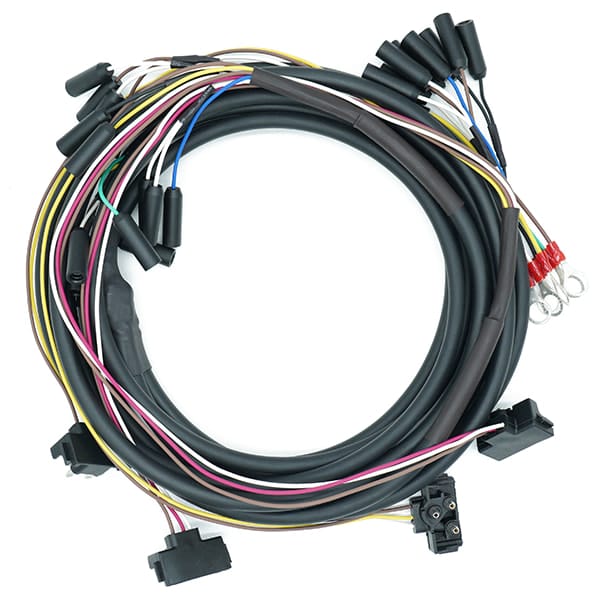
A custom wire harness keeps wires neat and tidy. It stops wires from getting messy. This helps gadgets work better and last longer. A custom harness is made to fit just right. It saves space and looks clean. It also makes fixing wires easy. These harnesses are used in cars, planes, and gadgets. They keep wires safe from damage. A wire harness is a wise choice. It keeps everything working smoothly. It also makes gadgets safer to use. Neat wires mean fewer problems and a longer life for your gadget. Custom Wire Harness Helps to Makes Things Work A wire harness is like a special box for wires. It holds many wires together. The wires stay in place and don't get lost. This helps things work. You can use the harness in cars, machines, and other things. It helps everything stay neat. The wires do not get tangled. A custom wire-harness is a simple way to make sure everything works well. How Custom Wire Harness Saves Time A wiring harness is very helpful. It holds all the wires together. The cables are not messy. You do not need to figure out which wire goes where. Everything fits just right. The cables are prepared. You can start your work fast. It saves you time. When the wires are all together, the job is much easier. A wiring harness kit makes it so much faster to finish the work. How Wiring Specialties Make a Perfect Wire Harness Wiring specialities help make the best wiring harness. They make sure the wires are just right for your project. You do not need to worry about where to put the cables. A wiring harness fits your needs. It helps you do the work without mistakes. It is made for you. It is safe and easy....
Read More »