How We Build Wire Harness Drawings ?
بواسطة wpname 玩好 / 2024年 10月月月 1024月月 1024
نظرة عامة على ضرورة وأهمية بناء رسومات تسخير الأسلاك وأهميتها
wire harness drawings are essential for providing a clear and detailed representation of the harness layout, connection relationships, and component information. These drawings ensure the accuracy, reliability, and safety of the wiring harness. They illustrate the harness routing, including starting points, endpoints, and intermediate connection points, as well as the harness path. Moreover, the drawings depict the connection methods and relationships of each wire within the harness. As the primary source of information for wiring harness production, these drawings play a fundamental and critical role in the manufacturing process.
رسومات تسخير الأسلاك المبنية من رسومات العملاء:
عملية QL-Custom من استلام الاستفسار إلى تقديم الرسم لمراجعة العميل :
عند تلقي استفسار، بما في ذلك رسومات أو عينات العميل، يقوم مهندسونا بتحديد استراتيجية التوريد، سواء كانت مواد أصلية أو محلية. ثم يحصلون على عروض الأسعار من عدة موردين، ويقارنون الأسعار لتقديم أفضل خيار للعميل. بعد تأكيد السعر، يتم تقديم طلب عينة. يقوم المهندسون بإنشاء الرسومات بناءً على المعلومات أو العينات المقدمة من العميل. وبعد المراجعة الداخلية والموافقة عليها، يتم إرسال الرسومات إلى العميل لتأكيدها.
اعتبارات الرسم والتفاصيل - تحليل رسم العملاء لإنشاء الرسم الخاص بنا:

Wire Harness Drawings
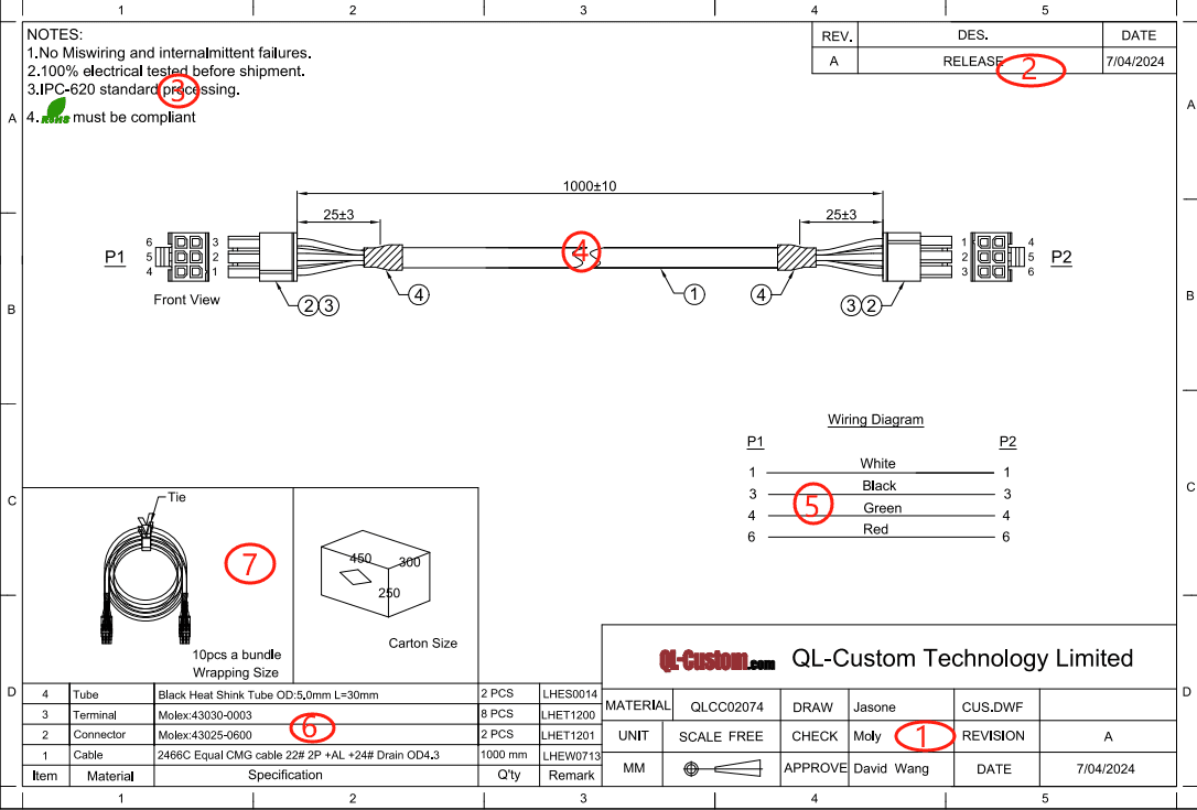
كما هو موضح أعلاه، يتكون الرسم النموذجي من سبعة أقسام رئيسية:
- معلومات الرسم: رقم الجزء الخاص بالعميل، ورقم الجزء الداخلي، والقائم بالصياغة، والمراجع، ومستوى المراجعة، والتاريخ، إلخ.
- تاريخ المراجعة: تفاصيل أي تغييرات تم إجراؤها على الرسم.
- متطلبات الجودة والاختبار: المعايير والاختبارات المحددة التي يجب أن تفي بها الأحزمة.
- تخطيط ثنائي الأبعاد: عرض شامل يوضح موضع المكونات وأطوال الأسلاك وتفاصيل التصنيع المهمة الأخرى.
- مخطط الدائرة: يوضح التوصيلات من نقطة إلى نقطة داخل الحزام.
- قائمة المواد (BOM): يسرد جميع المكونات، بما في ذلك الأسلاك والأطراف والموصلات والأغلفة، مع الكميات وأرقام الأجزاء الداخلية.
- معلومات التغليف: يحدد طريقة التغليف ووضع العلامات على الحزام.
wire harness drawings are essential in any manufacturing industry, serving as technical documents that communicate product structure, dimensions, shape, and other requirements. Production commences only after both parties have reviewed and approved the drawings.
إنشاء الرسومات من العينات :
عند تزويدنا بعينة، نتبع الخطوات التالية:
- وضع العلامات: كل سلك وموصل موسوم بدقة (على سبيل المثال، P1، P2، P3...) لتحديد موضعه بوضوح.
- التحقق من الدائرة: يتم تشغيل العينة للتأكد من الدائرة المقابلة لكل سلك.
- القياس: يتم وضع العينة بشكل مسطح، باستخدام الموصل الموجود في أقصى اليسار كنقطة مرجعية. يتم أخذ قياسات دقيقة بين الموصلات لتحديد أطوال الأسلاك. حفظ السجلات بدقة أمر بالغ الأهمية لتجنب الأخطاء.

Wire Harness Drawings
وبناءً على هذه الخطوات، يتم إنشاء رسم تخطيطي أولي ومخطط دائرة كهربائية. يتم تصوير كل موصل، ويتم استخدام الموارد عبر الإنترنت لتحديد النموذج المقابل وتأكيد كميات المكونات. يتم بعد ذلك تجميع هذه المعلومات في قائمة BOM. وأخيرًا، يتم تقديم الرسم التخطيطي ومخطط الدائرة الكهربائية وقائمة المكونات إلى المصمم لإنشاء الرسم الرسمي.
الفرق بين المواصفات والرسومات :
In the wire harness drawings industry, a specification document outlines the function, quality, and performance requirements of a specific component. It details technical parameters, dimensions, materials, packaging, and other relevant information. On the other hand, a wiring harness drawing visually represents the harness layout within a vehicle or electrical system, showing connector locations and wire routing.
أدوات الرسم في QL-Custom:
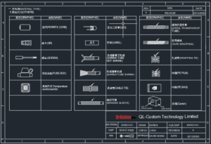
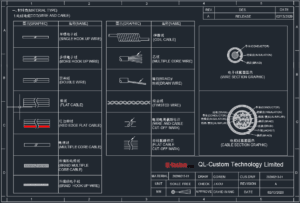
QL-مخصص has build a complete design of wire harness symbols how to express

Wire Harness Drawings

Wire Harness Drawings

Wire Harness Drawings
CAD - فوائد التصميم بمساعدة الحاسوب (CAD) - فوائد الرسومات ثنائية الأبعاد:
برنامج CAD هو أداة تصميم قوية تتيح الرسم والقياس الدقيق، مما يقلل من الأخطاء البشرية ويعزز دقة التصميم. تسهّل ميزات الرسم والتحرير القوية التي يتميز بها، بالإضافة إلى التوافق مع تنسيقات ملفات متعددة، تبادل البيانات بسلاسة.
Pro-E و Solidworks و UG - مزايا تصميم الموصلات:
Pro-E: يشتهر برنامج Pro-E بقدراته القوية في النمذجة الهندسية، خاصةً في نمذجة الأسطح، ويتفوق في المحاكاة والتصميم البارامترى.
سوليدووركس:
تلبي Solidworks، سهلة الاستخدام والبديهية، مجموعة واسعة من احتياجات التصميم الصناعي بفضل مجموعة ميزاتها الشاملة.
جامعة:
برنامج النمذجة ثلاثي الأبعاد كامل الميزات، يتميز برنامج UG بهيكلية قوية وقدرات شاملة تغطي جميع جوانب التصميم تقريبًا.
يمكن أن تساعدك QL-Custom في إنشاء أي رسومات تسخير الأسلاك من مخططات الأسلاك البسيطة إلى المعقدة
في الختام، جميع خيارات البرامج الثلاثة مناسبة تمامًا لتصميم الموصلات. يعتمد الاختيار في النهاية على التفضيلات الشخصية ومتطلبات المشروع ونقاط القوة المحددة لكل برنامج.