The Wire Cable Harness Drawing Standards
By Tina / 2025年4月23日
Importance of the Wire and Cable Harness Drawing
In the realm of modern engineering and design, wire cable harness drawings hold paramount importance. These drawings serve as blueprints that detail the intricate layouts of wiring systems, ensuring that each component is correctly connected and functioning as intended. Without precise drawings, the likelihood of errors increases, which can lead to system failures, costly repairs, and even hazardous situations. For engineers and designers, mastering wire cable harness drawing standards is not just an option but a necessity to ensure the reliability and safety of their projects.
Wire cable harness drawings are essential for several reasons. Firstly, they provide a visual representation of the electrical connections and layout, making it easier for engineers to understand and communicate the design to others involved in the project. This includes manufacturers, technicians, and quality control personnel. A well-drafted harness drawing eliminates ambiguities, reducing the risk of misinterpretation and ensuring that everyone is on the same page.
Secondly, these drawings play a critical role in the manufacturing process. They guide the assembly of the wire harness, specifying the lengths of wires, the types of connectors, and the routing paths. This level of detail is crucial for ensuring that the harness fits correctly within the physical constraints of the application, whether it’s in an automotive, aerospace, or industrial setting. Accurate drawings help streamline the production process, minimize errors, and enhance the overall quality of the final product.
Mastering Wire Cable Harness Drawing Standards: A Comprehensive Guide for Engineers and Designers
To master wire cable harness drawing standards, engineers and designers must familiarize themselves with industry norms and best practices. These standards are established by organizations such as the International Electrotechnical Commission (IEC), the Institute of Electrical and Electronics Engineers (IEEE), and the National Electrical Manufacturers Association (NEMA). Understanding these standards is crucial for creating designs that are not only functional but also compliant with regulatory requirements.
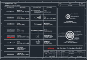
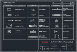
One of the fundamental aspects of wire cable harness drawing standards is the use of standardized symbols and notations. These symbols represent various components such as wires, connectors, terminals, and splices. By using standardized symbols, engineers can create drawings that are universally understood, facilitating easier collaboration and communication. Additionally, adherence to these standards ensures consistency across different projects, making it easier to maintain and update designs over time.
Another key element of mastering wire cable harness drawing standards is understanding the different types of drawings used in the design process. These include schematic diagrams, wiring diagrams, and layout drawings. Each type of drawing serves a specific purpose and provides different levels of detail. For example, schematic diagrams show the electrical connections and relationships between components, while wiring diagrams provide detailed information on wire routing and connections. Layout drawings, on the other hand, illustrate the physical arrangement of the harness within the application. By mastering these different types of drawings, engineers can create comprehensive and accurate designs.
The Wire and Cable Harness Components Drawings Standards
Wire and cable harness components drawings standards are essential for ensuring that all parts of the harness are correctly specified and documented. These standards cover various aspects, including the identification of components, the use of reference designators, and the specification of wire types and sizes. By adhering to these standards, engineers can create detailed and accurate component drawings that facilitate the assembly and maintenance of the wire harness.
One of the key components of wire and cable harness drawings is the use of reference designators. These designators are unique identifiers assigned to each component in the harness, such as connectors, terminals, and splices. Reference designators help ensure that each component is correctly identified and located within the drawing, reducing the risk of errors during assembly. Additionally, they provide a standardized way of referencing components in documentation and communication, making it easier to track and manage parts throughout the lifecycle of the harness.
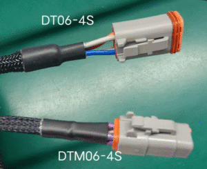
Another important aspect of wire and cable harness components drawings standards is the specification of wire types and sizes. Different applications require different types of wires, each with its own set of characteristics such as insulation material, conductor size, and temperature rating. By specifying the correct wire types and sizes in the drawings, engineers can ensure that the harness meets the performance and safety requirements of the application. This level of detail is crucial for preventing issues such as overheating, voltage drops, and electrical interference.
How to Draft Wire and Cable Harness Wiring Diagrams
Drafting wire and cable harness wiring diagrams is a critical skill for engineers and designers. These diagrams provide detailed information on the electrical connections and routing of wires within the harness, making them essential for both the design and manufacturing processes. To create accurate and effective wiring diagrams, engineers must follow a systematic approach and adhere to industry standards.
The first step in drafting a wiring diagram is to gather all necessary information about the components and their connections. This includes details such as the types of connectors, terminals, and wires used in the harness, as well as the electrical characteristics of each component. Engineers should also consider the physical constraints of the application, such as the available space for routing the harness and the environmental conditions it will be exposed to. By thoroughly understanding the requirements and constraints, engineers can create a wiring diagram that meets all design criteria.
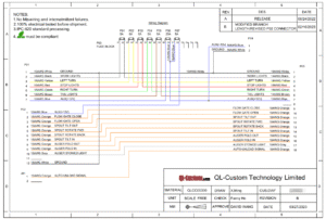
Once the necessary information is gathered, engineers can begin creating the wiring diagram. This involves drawing the wires and connections between components, using standardized symbols and notations to represent each element. It’s important to ensure that the diagram is clear and easy to read, with all connections accurately depicted. Engineers should also include annotations and labels to provide additional information, such as wire lengths, connector types, and reference designators. By following these best practices, engineers can create wiring diagrams that are both accurate and comprehensive.
What Software Can Build Wire and Cable Harness Drawings
In today’s digital age, specialized software tools have become indispensable for creating wire and cable harness drawings. These tools offer a range of features and functionalities that streamline the design process, improve accuracy, and enhance collaboration. Engineers and designers can choose from various software options, each with its own set of capabilities and benefits.
One of the most popular software tools for wire and cable harness design is AutoCAD Electrical. This software provides a comprehensive set of tools for creating schematic diagrams, wiring diagrams, and layout drawings. AutoCAD Electrical offers features such as automated wire numbering, component tagging, and error checking, which help ensure accuracy and consistency in the drawings. Additionally, the software integrates with other Autodesk products, making it easy to collaborate with other team members and manage design data.
Another widely used software tool is SolidWorks Electrical. This software combines electrical schematic design with 3D modeling capabilities, allowing engineers to create detailed and accurate harness designs. SolidWorks Electrical offers features such as real-time collaboration, automated routing, and bill of materials generation, which streamline the design process and improve efficiency. The software also integrates with other SolidWorks products, enabling seamless collaboration and data management.
For those looking for a more specialized solution, Mentor Graphics’ Capital is a powerful software tool specifically designed for wire and cable harness design. Capital offers advanced features such as automated design rule checking, signal integrity analysis, and manufacturing documentation generation. The software also supports collaboration and data management, making it an ideal choice for complex and large-scale projects. By leveraging these software tools, engineers can create high-quality wire and cable harness drawings that meet industry standards and project requirements.
Rapid Harness, is a good wire harness drawing tool but need to pay for it monthly.
What Company Will Need to Build Wire and Cable Harness Drawings
Companies across various industries rely on wire and cable harness drawings to ensure the reliability and efficiency of their electrical systems. These drawings are crucial for industries such as automotive, aerospace, industrial machinery, and consumer electronics, where complex wiring systems are integral to the functionality of the products. Understanding the specific needs of each industry can help engineers create tailored harness designs that meet the unique requirements of their applications.
In the automotive industry, wire and cable harness drawings are essential for designing the electrical systems of vehicles. These drawings detail the connections between components such as sensors, actuators, and control units, ensuring that the electrical system operates reliably and efficiently. Automotive manufacturers rely on accurate harness drawings to guide the assembly process, reduce production errors, and ensure compliance with safety standards. Additionally, these drawings are used for troubleshooting and maintenance, helping technicians quickly identify and resolve issues.
The aerospace industry also heavily relies on wire and cable harness drawings for designing the electrical systems of aircraft. These drawings must meet stringent safety and performance requirements, as any failure in the electrical system can have catastrophic consequences. Aerospace engineers use harness drawings to ensure that all components are correctly connected and that the wiring is properly routed to minimize electromagnetic interference and physical damage. Accurate and detailed harness drawings are crucial for ensuring the safety and reliability of aircraft electrical systems.
In the industrial machinery sector, wire and cable harness drawings are used to design the electrical systems of various types of equipment, such as robots, conveyors, and control panels. These drawings provide detailed information on the connections between components, helping ensure that the machinery operates correctly and efficiently. Accurate harness drawings are essential for guiding the assembly process, reducing production errors, and ensuring compliance with industry standards. Additionally, these drawings are used for maintenance and troubleshooting, helping technicians quickly identify and resolve issues.
What is Wire and Cable Harness Engineering Drawing – The Process Breakdown Guiding Drawings
The process of creating wire and cable harness engineering drawings involves several steps, each of which plays a crucial role in ensuring the accuracy and reliability of the final design. By following a systematic approach, engineers can create detailed and comprehensive drawings that meet industry standards and project requirements.
The first step in the process is to gather all necessary information about the components and their connections. This includes details such as the types of connectors, terminals, and wires used in the harness, as well as the electrical characteristics of each component. Engineers should also consider the physical constraints of the application, such as the available space for routing the harness and the environmental conditions it will be exposed to. By thoroughly understanding the requirements and constraints, engineers can create a preliminary design that meets all design criteria.
Once the preliminary design is complete, engineers can begin creating the detailed engineering drawings. This involves drawing the wires and connections between components, using standardized symbols and notations to represent each element. It’s important to ensure that the drawings are clear and easy to read, with all connections accurately depicted. Engineers should also include annotations and labels to provide additional information, such as wire lengths, connector types, and reference designators. By following these best practices, engineers can create detailed and accurate engineering drawings that guide the assembly process.
The final step in the process is to review and validate the engineering drawings. This involves checking the drawings for errors and inconsistencies, ensuring that all components are correctly identified and located. Engineers should also perform design rule checks to verify that the harness meets all performance and safety requirements. Once the drawings are validated, they can be used to guide the assembly process and ensure the accurate and reliable construction of the wire and cable harness.
Contact QL-Custom to Explain More About Wire and Cable Harness Drawings
For those looking to gain a deeper understanding of wire and cable harness drawings, contacting industry experts can provide valuable insights and guidance. One such expert is QL-Custom, a company specializing in the design and manufacture of custom wire and cable harnesses. With years of experience and a team of skilled engineers, QL-Custom can provide expert advice and support for all aspects of wire and cable harness design.
QL-Custom offers a range of services to help engineers and designers master wire and cable harness drawing standards. These services include custom harness design, prototyping, and manufacturing, as well as technical support and consultation. By working with QL-Custom, engineers can gain access to the latest industry knowledge and best practices, ensuring that their harness designs meet all performance and safety requirements.
Additionally, QL-Custom provides training and educational resources to help engineers and designers improve their skills and knowledge. These resources include webinars, workshops, and technical articles, covering a wide range of topics related to wire and cable harness design. By taking advantage of these resources, engineers can stay up-to-date with the latest industry trends and advancements, and continuously improve their expertise in wire and cable harness drawing standards.
In conclusion, mastering wire cable harness drawing standards is essential for engineers and designers looking to create high-quality, reliable, and efficient harness designs. By understanding industry norms, using specialized software tools, and seeking guidance from experts like QL-Custom, engineers can elevate their skills and create designs that stand out in the competitive landscape of engineering and design. Whether you are an experienced engineer or a budding designer, embracing the challenge of mastering wire cable harness drawing standards will undoubtedly lead to success in your projects and career.