Top Best Automotive Wiring Harness Company
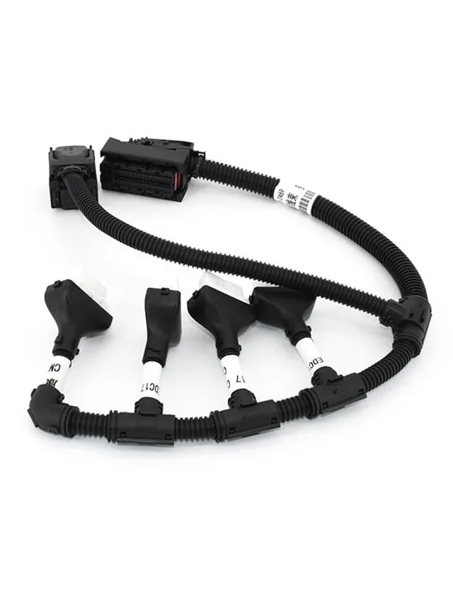
Cars today have many wires inside. These wires help things like lights, buttons, radios, and the engine work right. The Automotive Wiring Harness carries power from one part to another. They also carry messages that tell the car what to do. Without these wires, the car would not work at all. So, having strong and smart cables in the car is very important. QL-Custom Technology Ltd. is the best provider for wire harness. They are very experienced harness manufacturers. This company makes sure that all their products are good quality. They Work very hard to satisfy you with your products. QL-Custom Technology Ltd. has an expert team that always tries something new to get updated. What Makes a Great Automotive Wiring Harness A good harness wiring should be robust. It should not melt or break, even in hot or cold places. It should be safe from water and dirt. The wires must be clean and made just right to fit your car's needs. Each wire is covered with strong plastic to keep out dirt and water. The plugs at the ends must fit tight and not come loose. An innovative design saves time and money during building. At QL-Custom, they test each wire harness many times to ensure it is just right before sending it to the customer. They want it to work well right away. Why Choose QL-Custom Technology Ltd. QL-Custom Technology Ltd. Is the exact company for producing the best and exact automotive wiring harness. They make the best items by following ISO9001:2015. They also obey the IATF16949 rules. They try their best to improve their product by following the rules. They only use the best materials to make parts. Their workers are trained and careful. They use innovative tools that help build parts fast and...
Mehr lesen "Custom Car Wire Harness Manufacturer
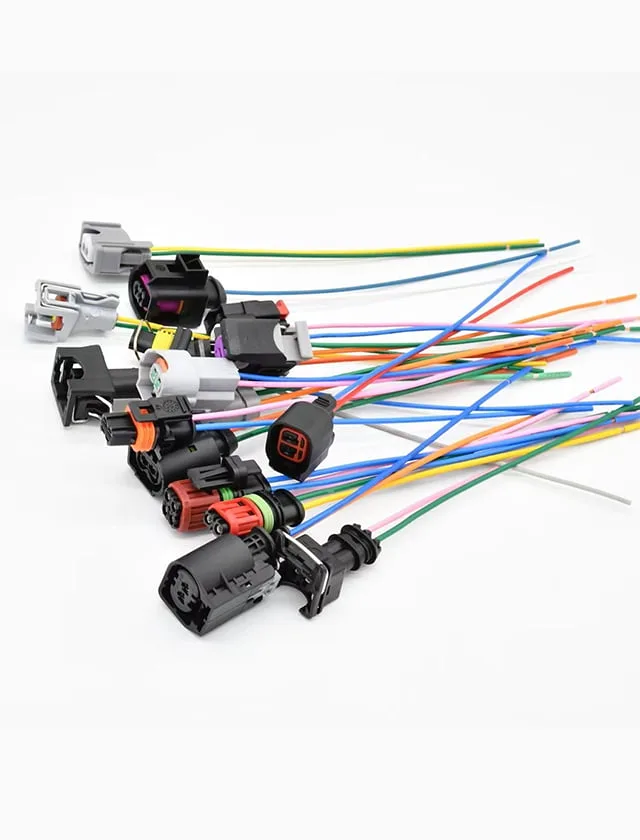
Seeking strong, safe, and long-lasting Custom Car Wire Harness? QL-Custom Technology Ltd. makes special custom car wire harnesses that fit every need. High-quality wires help cars run smoothly, ensuring they work well for a long time. Every wire is made with great care and attention. The goal is to give the best wires that are safe, powerful, and built to last. A car needs good wires to work the right way. A lousy wire setup can cause serious issues. Wires connect many essential car parts. If the cables are not correct, the car might not start. Lights may stop working. The battery could lose power quickly. This is why a good wire setup is so vital. It makes sure power flows the right way. It also protects against electrical failures. It keeps the car safe and working at its best. Why Choose Automotive Wire Harnesses Works Better & Lasts Longer A custom wire setup makes the car run better and last longer. Automotive wiring harness issues can lead to big trouble. Weak wires may cause short circuits or even engine failure. A strong custom car wire harness is designed to stop these issues before they happen. It is built to handle heat, shaking, and harsh conditions. These wires will stay strong and work right regardless of the road or weather. Made Just for Your Car Every car is different. A custom-made wire setup fits perfectly. It connects all parts in the best way. A perfect fit means easier installation and better performance. A car’s electrical system must match its wiring exactly. A custom harness keeps the setup clean, without extra wires or messy links. Everything is placed in the right spot to ensure the car works at its best. Best Parts & Materials Only top-quality wires, covers, and connectors...
Mehr lesen "How to Identify a High-Quality Automotive Wire Harness
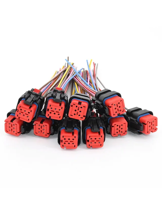
An Automotive Wire Harness carries power to different parts, so they have to work right. Without a good harness, many car parts will not work. A wire harness kit connects lights, the engine, and sensors. A strong harness keeps a car safe. It must handle heat, cold, and water. A weak harness can break or stop working. This can cause significant problems, like lights failing or the engine stopping. A well-made auto electrical wiring harness helps the car run smoothly. Find a great automotive wiring harness and show why QL-Custom Technology Ltd. is the best choice. What is a Automotive Wire Harness An Automotive Wire Harness is a group of wires, connectors, and terminals. These parts send power and signals to different parts of the car. This harness controls headlights, brakes, the engine, and sensors. Bad electrical wiring harnesses can cause big problems. Bad wiring can make lights flicker, stop signals from working, or even break the car. A good harness keeps the wires neat and safe from damage. Choosing a strong automotive wiring harness is vital for safety. A weak harness can fail suddenly or even cause an electrical fire. What Makes a Automotive Wire Harness Good Strong Materials A good automotive wire harness is made from strong materials. Copper wires are best because they carry power well. The covering should protect against heat, water, and damage. This helps the harness last longer. A weak harness can crack or break. A good car wiring harness must handle heat, cold, and rough roads. Strong wires make sure power flows smoothly. The covering should be thick to prevent short circuits. Safe and Certified An excellent car wiring harness follows safety rules. Certifications like ISO and IATF16949 show the product is made well. QL-Custom Technology Ltd. follows these rules to make...
Mehr lesen "What Testing Methods Ensure a Reliable Custom Wire Harness
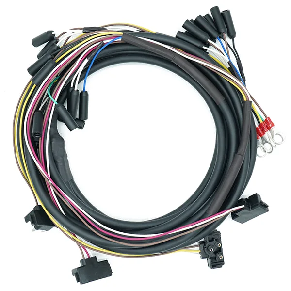
A custom wire harness is a bundle of wires put together to connect different parts of a machine. It keeps wires neat and safe. Without a good quality wire harness machine could be damaged. Even worse, bad wiring can be dangerous for people using the machines. This is why testing is crucial. Testing helps ensure that harnesses wire is strong and safe. It also ensures that the harness will last long and not fail when needed. A good wire harness keeps machines running smoothly and safely. Our Promise at QL-Custom Technology Ltd. At QL-Custom Technology Ltd., we focus on making the best wire harnesses. Every harness we make is tested carefully to ensure it is strong and works well. Quality comes first, and we do not take shortcuts. We make sure every harness is built to handle harsh conditions. We aim to create harnesses that last a long time and help machines run without problems. Our wire harnesses are designed to work well in any situation. They work well on all small devices or big machines. Why Testing Custom Wire Harness Matters Without testing there could be many kinds of issues. It is a vital part of making wire harnesses. An untested wire harness can cause many problems to the machine. It can find the damaged parts. It also ensures that the harness will last and not break suddenly. Another big reason for testing is safety. A wire harness must follow strict safety rules. A bad harness could lead to power failures, electric shocks, or fires. Testing helps prevent these Issues. Testing makes sure every wire is in the right place and working correctly. Testing also checks if the harness can handle different conditions. Machines are used in places that can be hot, cold, wet, or dry. A...
Mehr lesen "10 Benefits of a High-Quality Automotive Wire Harness
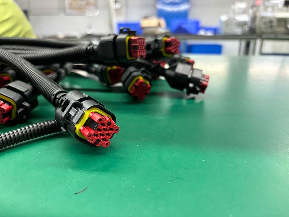
Automotive wire harness keeps all the wires together and safe. It helps us in many ways. Without it, wires inside vehicles will be messy and it will be very hard to find the exact wire when needed. And it will be dangerous for us. But with this harness the wires will be protected from the bad weather and there will be no issues. Keeps Wires Neat and Safe A wiring harness keeps all the wires together. This stops them from getting messy or broken. Loose cables can cause big problems. They can be hard to fix and might stop working. A neat setup makes it easy to find and resolve any issues. It also makes adding new parts simple. A clean system saves time and prevents mistakes. A good harness keeps the whole system safe and strong. Prevents Fires and Short Circuits A strong wire harness keeps wires safe. It stops short circuits and lowers the risk of fire. Exposed wires can cause dangerous sparks. A good harness covers the wires and protects them. This keeps the car and passengers safe. A weak system can overheat and cause risks. A strong harness stops that. It keeps everything running smoothly and safely. Keeps Power Moving Right A custom wiring harness makes sure power flows well. It sends power to the right places at the right time. Weak wires can make the car stop working. Bad connections can make lights flicker or slow down the engine. This can make the car unsafe to drive. A strong harness keeps power steady and helps the vehicle run better. A good harness means no sudden stops or failures. Protects Wires for a Long Time Weak wires wear out fast and cause problems. A strong harness keeps the system working for a long time. This means...
Mehr lesen "Difference Between Cable Assemblies and Wire Harnesses
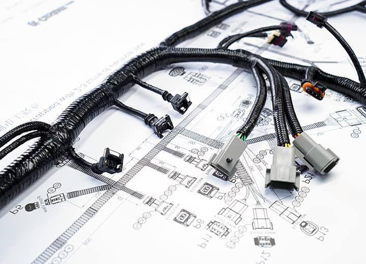
Wires carry power. They must be safe and organized. A wire harness holds wires together. It keeps them neat. Cable assemblies do the same but adds protection. It has a strong outer layer. This layer guards against heat, water, and damage. Wire harnesses are best for keeping wires in place. Cable harness assembly works well in harsh conditions. Cable Assemblies: the basics It covers a group of wires in a hard cover. It keeps the wire safe from many things. In bad conditions it keeps the wires safe. There are many sizes available. You can also find many shapes of it. The cover is very hard; it is made of plastic or rubber. This cover helps wire to last long in harsh weather. Industries need these because these make the wire safe. These places include hospitals, construction sites, and power plants. Wires in these places must stay safe from bad weather, heavy movement, and chemicals. It makes sure they stay working for a long time. It helps machines to work properly. What is Wire Harness? It brings all the wires together. It does not have any hard covers. Instead, it has a light cover to keep the wires neat and in place. Wire harnesses are found inside cars, TVs, and household machines. They work best in clean and dry places. A wire harness helps wires stay in the right place. It stops the wires from getting mixed. Loose wire can cause problems. It keeps the wires together and in a good position. With a wire harness you can easily find a wire when you need it. These are not so costly. Wire harnesses are used in many places. These devices need well-organized wires but do not need heavy protection. Key Differences Between Assemblies & Harnesses Protection: Cable-assemblies...
Mehr lesen "Superior Custom Wire Harness for the right Job
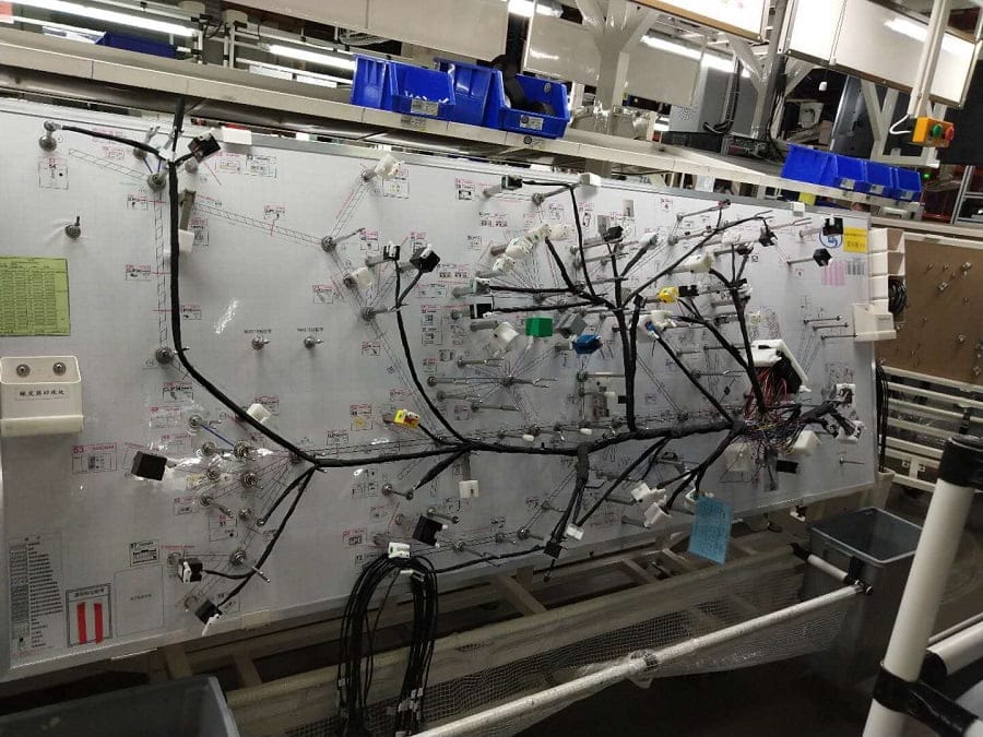
The custom wire harness connects machine parts while keeping wires organized and secure. It ensures electrical components function smoothly. Regular cables can be messy. They get tangled and break easily. A custom harness is made for a specific job. This helps machines work better and last longer. It also enhances safety, which is why industries like automotive, aerospace, and heavy machinery depend on them. Wire harnesses come in various sizes, lengths, and coverings to keep wires securely in place. This stops them from moving or tangling. Keeping wires neat helps air flow better. It also reduces heat. This makes machines work more smoothly. Wire harnesses are used in homes and factories. They keep electric connections strong and safe. Engineers use them to enhance the safety and maintainability of electrical systems. QL-Custom Technology Ltd. manufactures high-quality wire harnesses. Our products are safe and high quality. Many industries trust us. We test every harness to make sure it is the best. We always look for new ways to improve. Our team works with customers to make the right products for them. Our harnesses are easy to install. They last a long time and work well. Why Choose Us for Custom Wire Harnesses? QL-Custom Technology Ltd. is ISO9001:2015 certified. This site is expert in custom wire harnesses. QL-Custom also makes over-molding cable assemblies. Our team has many years of experience. Our products are trusted by the electronics, medical, automotive, robotics, military, clean energy, and camera industries. Our team focuses on innovation, quality, and customer happiness. If you need a custom wire harness, choose us! Making Custom Cable Harnesses: Technical Processes Using advanced machinery and stringent quality control processes, we produce high-quality custom wire harnesses. Our machines use automation to make parts fast and correct. EDM machining shapes parts with great...
Mehr lesen "Maximum quality Automotive-wire-harness at ease

An automotive wire harness is like a bunch of tiny ropes that carry power and signals to different parts of the car. It helps turn on the lights, run the engine, play music on the radio, and blow cold air on hot days! Without it, the wires would be all messy, and the car would stop working. The harness keeps everything neat so the car can work properly. It is important because it keeps the car's wires safe. If the cables get tangled, they can break, and things in the car might stop working! The lights might not turn on, the radio might be silent, or the vehicle might not start! The harness keeps everything in place so the car can work safely daily. It also stops wires from rubbing together and wearing out too fast. Think of it like a superhero keeping the cables safe! QL-Custom makes special wiring harnesses! These wires help cars, trucks, and big machines move and work. Machines need wires to run, and we make sure the cables are safe and strong. If machines do not have good wires, they stop working. But with QL-Custom, everything works great! We use small parts and big parts. We put all the cables in the right place. We make them strong so they do not break. We help people get the right wires. We take time to make sure everything is just right! Parts of an automotive-wire-harness kit A wire harness kit has many small parts that help it work. Each part has a big job to do: Wires are like tiny roads that carry power to different car parts. Connectors – These help wires join so electricity can move from one place to another. Covers – These wrap around wires like a blanket to keep them safe...
Mehr lesen "How Are Automotive Wire Harnesses Manufactured
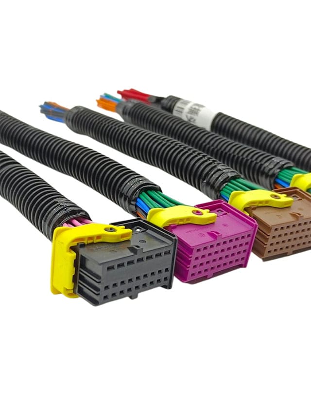
Cars have many electric parts. Lights, radios, and engines all need power to work. A Automotive Wire Harness is a bundle that helps send power to the right places. A car's electric system would not work well without a wire harness. Making a wire harness starts with cutting wires to the correct length. Then, the cables are put into groups so they do not get messy. A cover is added to protect the cables from heat, water, and damage. After that, the wire harness is tested to make sure it works. A good wire harness helps cars run smoothly and safely. How Do Engineers Design a Car Wire Harness? Before making a car wire harness, engineers have to plan it out. They decide where each wire should go. And make sure it connects to the right parts, like the lights, engine, or sensors. If they make a mistake, the car might not work. The wires also need to be safe. They must handle heat, vibrations, and moisture without breaking. A good design helps the car wire harness last long and keeps the car running smoothly. Choosing the Right Materials A wire harness is a set of wires. These wires carry power to different car parts. They need to be strong and safe. If they get too hot or break, they can cause problems. A cover protects them from water, dirt, and heat. Without this cover, the wires may fail. If that happens, the car may not work. A good wire harness stops fires and short circuits. Strong materials help the car run well for a long time. Cutting and Stripping the Wires After picking the right materials, the wires must be cut to the correct size. If a wire is too short, it will not reach its part. If it...
Mehr lesen "Does OBD GPS Tracking Cables Enhance Vehicle Security
Keeping a car safe is very important for every car owner. Cars can get stolen very fast, and that can be very stressful. However, with an OBD GPS tracking cable, car owners can always know where their car is. This small cable plugs into the car and connects to a GPS tracking system. The system sends signals to a phone or computer. The owner can see the exact location of the car on a map. If the car is stolen, it can be found very fast. This is why thes tracking cables are handy. Thieves know that cars with GPS tracking are easy to find, so they do not want to steal them. These cables are small, easy to install, and do not cost much. What is an OBD GPS Tracking Cable? This cable is a small but beneficial wire. It helps a GPS tracker work inside your car. This cable plugs into the OBD port, a unique slot inside most cars. Every modern car has this port. The OBD cable gives power to the GPS tracker, so you do not need to charge it or use extra batteries. Setting it up is very simple. You do not need any tools. You do not need a mechanic. You just plug it in, and it starts working right away. It is one of the easiest ways to track a car. How Does the Cable Work? The OBD cable connects the GPS tracker to your car’s system. Once plugged in, the tracker turns on. It starts sending updates about your car’s location. You can check where your vehicle is at any time. You can use an app or website on your phone, tablet, or computer. This tracking system is helpful in many ways. Families can keep track of their cars and...
Mehr lesen "